BL-11A Soft X-Ray Grazing Incidence Monochromator Station
Spokesperson :Yoshinori KITAJIMA
5641(PHS:4279)
yoshinori.kitajima@kek.jp
1. Outline
BL-11A provides soft X rays in the energy range between 70 eV and 1900 eV with a grazing-incidence monochromator from a bending-magnet source. As there are several stations available at the Photon Factory which cover similar energy ranges with undulator sources, such as BL-16B, BL-13C, and BL-2C, the optics of BL-11A has been designed especially under consideration of the availability for wider energy range so that EXAFS spectra for light elements such as C, N, O, F, Na, Mg, and Al can be measured.

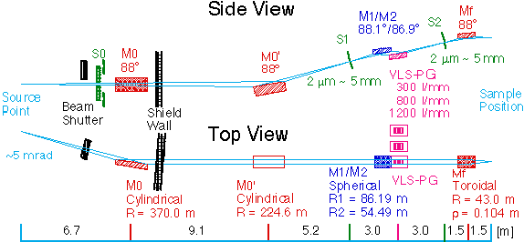
Fig. 1: Layout of BL-11A
Synchrotron radiation from the bending magnet B11 (maximum horizontal acceptance of 5 mrad) is reflected by two cylindrical mirrors, M0 and M0', monochromated and focused by a grazing-incidence monochromator consist of spherical mirror, M1 or M2, and varied-line-spacing plane grating, G, between entrance and exit slits, S1 and S2, finaly refocused by a toroidal mirror, Mf, to the sample position. S0 is an aperture to accept center or off-axis beams for linearly or elliptically polarized soft X rays, respectively. Though not shown in the figure, a double-mirror system can be inserted between S2 and Mf to eliminate higher-order reflection and a control software for simultaneous scan of the grating and the double mirror is prepared.
The monochromator is equipped with mechanisms to exchange two spherical mirrors, M1 and M2, for different included angles, and three gratings with different groove densities, 300 l/mm, 800 l/mm, and 1200 l/mm, according to the appropriate energy ranges, which enables us to use a wide energy range of 70 - 1900 eV without breaking vacuum. Energy scan is achieved by the rotaion of the grating only with a sine-arm mechanism, ensuring high stability and reliability for XAFS measurements. Control system is also simple.
2. Performance
| Optics | Pre-Focusing Mirrors/Varied-Line-Spacing Plane Grating Monochromator/Refocusing Mirror |
|---|
| Energy Range | 70 eV - 1900 eV |
|---|
| Resolving Power | E/dE = 500 ~ 4000 |
|---|
| Spot Size | ~ 2 mm (H) x 0.5 mm (V) |
|---|
| Photon Flux | maximum ~1012 photons/s |
|---|
At present, three holographically recorded gratings with the groove densities of 300 l/mm, 800 l/mm and 1200 l/mm are installed and another mechanically-ruled grating of 800 l/mm is stored.

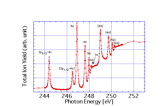
Fig. 2: Ar 2p photo-ion yield spectrum recorded with a mechanically ruled 800-l/mm grating and M2.
Figure 2 shows a total photo-ion yield spectrum of Ar gas in the Ar 2p excitation energy region recorded with a mechanically ruled 800 l/mm grating and M2. It is confirmed that the optical elements and those alignments are good enough by the clear observation of the transition to 7d. However, it is noted that the photon flux is much lower, typically two orders of magnitude, than undulator beamlines such as BL-16B.

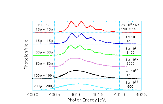
Fig. 3: N 1s-p* absorption spectra of N2 gas recorded with a mechanically ruled 800-l/mm grating and M2.
Figure 3 shows total photo-ion yield spectra of N2 gas in the N 1s-p* excitation energy region with various slit openings indicated up-left in the figures. Photon fluxes and resolving powers with a mechanically ruled 800-l/mm grating and M2 are also indicated in the up-right of the figures. With a holographically recorded grating of 800 l/mm, the achieved maximum resolving power is slightly lower than the mechanically ruled one, but the available photon flux is higher.

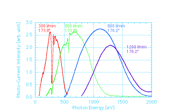
Fig. 4: Available flux distribution with holographically recorded gratings. Note the resolving powers are not constant because the slit opening is fixed in these measurements.
Figure 4 shows flux distribution spectra with holographically recorded gratings. Highly pure soft X rays up to 1900 eV are available with the holographically recorded gratings so that XAFS spectra on Na, Mg, Al K-edges can be measured (see example data).
3. Equippments
- Personal computer for monochromator control [Dell PC (Windows) with 3.5"FDD(2HD)]
- Software for monochromator control and XAFS measurements (LabView)
- Photon intensity monitor system (mesh and pico-Ammeter)
- Stages for vacuum chambers (1.5 m x 1.5 m, 1.5 m x 1.0 m, 1.5 m x 0.5 m x 2)
4. Remarks
- BL-11A does not have own vacuum chambers so that users should bring one. Many of experimental apparatuses of PF can be connected. Please contact the spokesperson for each apparatus.
- Sample chamber should be evacuated to < 10-6 Torr.
- Beam is ~2.04 m above the floor level but ~1.2 m from the above-mentioned stages at sample position. It comes 8 mm up when double mirror is inserted.
- Brief manual in Japanese is currently available on web.
5. References
- "Design report for the reconstruction the BL11A & D", KEK Report 95-4 (1995) (in Japanese).
- K.Amemiya, Y.Kitajima, T.Ohta and K.Ito, J. Synchrotron Rad., 3, 282 (1996).
- K.Amemiya, Y.Kitajima, Y.Yonamoto, T.Ohta, K.Ito, K.Sano, T.Nagano, M.Koeda, H.Sasai and Y.Harada, Proc. SPIE, 3150, 171 (1997).
- Y.Kitajima, K.Amemiya, Y.Yonamoto, T.Ohta, T.Kikuchi, T.Kosuge, A.Toyoshima and K.Ito, J. Synchrotron Rad., 5, 729 (1998).
- Y.Kitajima, Y.Yonamoto, K.Amemiya, H.Tsukabayashi, T.Ohta and K.Ito, J. Elec. Spectrosc. Relat. Phenom., 101-103, 927 (1999).
6. Publications
List of publications those registered to PF publication database is available.
Last modified: July 5, 2005.


