BL-13A/B Vacuum Ultraviolet and Soft X-Ray Spectroscopy Station for Surface Chemistry
Spokesperson: Kazuhiko MASE
6107(PHS4440)
mase@post.kek.jp
1. Outline
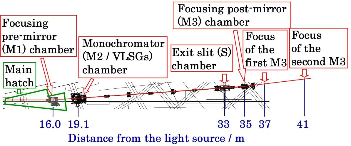
A vacuum ultraviolet and soft X-ray (VUV/SX) undulator beamline, BL-13A (Figs. 1 and 2), was made available to users on January 29, 2010. BL-13A is mainly dedicated to the study of surface chemistry, using angle-resolved photoelectron spectroscopy (ARPES), X-ray photoelectron spectroscopy (XPS), and X-ray absorption spectroscopy (XAS). Details of BL-13A have been described in previous papers [1-3]. Briefly, BL-13A is an undulator-based VUV/SX beamline that adopts a variable-included-angle Monk-Gillieson-type monochromator with varied-line-spacing gratings (VLSGs) [4]. The center of a planar undulator [5] is regarded as the source point for the monochromator, and no entrance slit is used. BL-13A consists of a focusing pre-mirror (M1), a plane mirror (M2), two VLSGs, (300 and 1000 lines/mm), an exit slit, and two focusing post-mirrors (M3, 2-m:2-m focusing; M3′, 2-m:6-m focusing). The 300- and 1,000-l/mm VLSGs cover the photon energy region of 30 – 300 eV and 100 – 1,600 eV, respectively. The monochromatized VUV/soft X-ray is refocused with M3 onto the sample position, which is located at 37.0 m from the light source. The base pressure of BL-13A is maintained below 1 × 10⁻⁸ Pa to prevent contamination of the optics by residual gases. BL-13A suffered damage from the Great East Japan Earthquake on March 11, 2011 but was again made available to users on October 3, 2011.
Fig. 1 Floor layout of BL-13A.
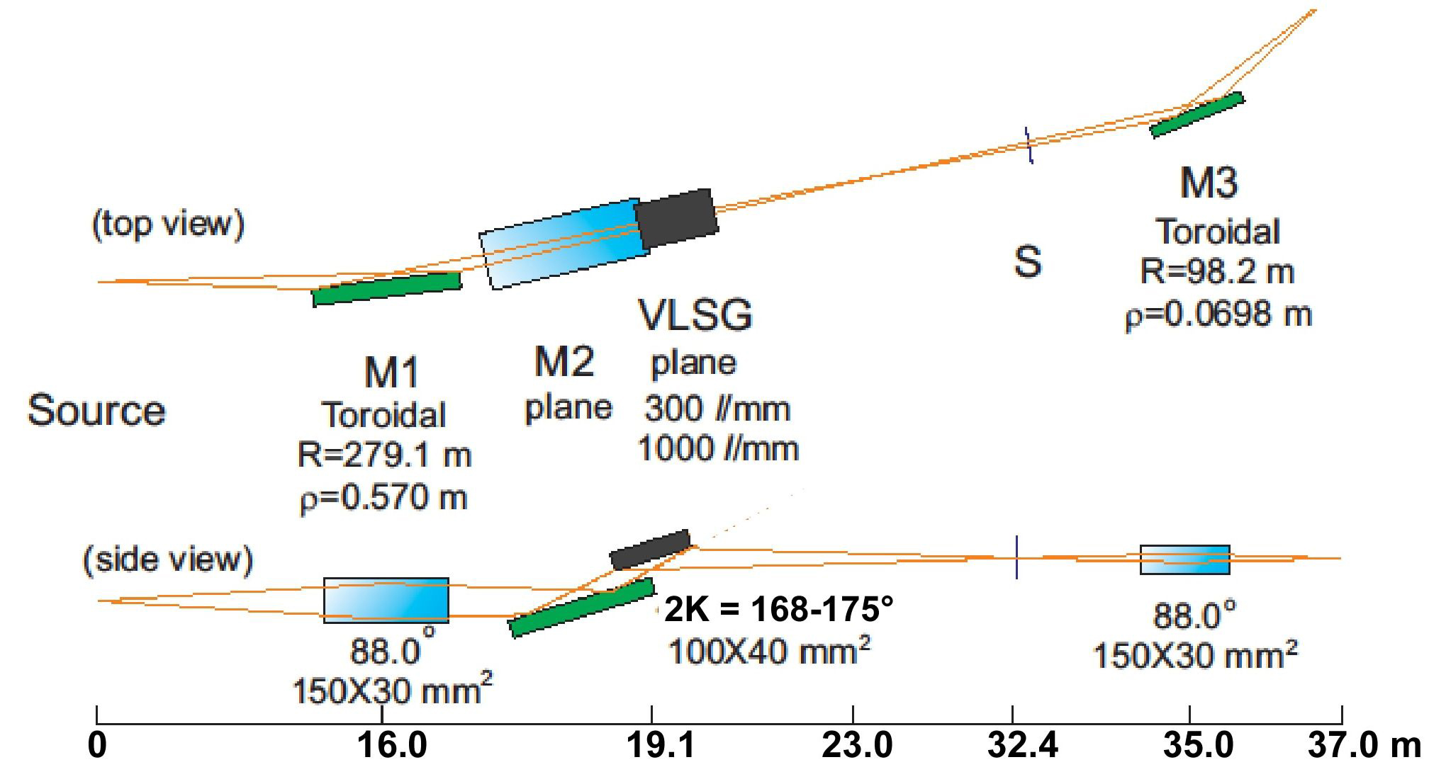
Fig. 2. Schematic layout of the optics of BL-13A.
2. Performance
The available energy region: 30 - 1600 eV.
Polarization: Horizontal linear polarization.
Typical photon intensity: 1012~108 photons/s. See Fig. 3 [3].
Typical photon energy resolution (E/ΔE): See the table below and Fig. 3 [3].
| Photon energy (eV) | 64.1 | 244.3 | 401.1 | 867 |
| E/ΔE for Gr = 300 line/mm, Slit width of 30 μm | 10,000 | 3,600 | - | - |
| E/ΔE for Gr = 300 line/mm, Slit width of 100 μm | 6,500 | 2,900 | - | - |
| E/ΔE for Gr = 1000 line/mm, Slit width of 30 μm | - | 7,700 | 7,100 | 7,200 |
| E/ΔE for Gr = 1000 line/mm, Slit width of 100 μm | - | 5,200 | 5,000 | 4,000 |
Typical beam size with a slit width of 40 μm at the first focal point:
About 210 μm (horizontal) × 40 μm (vertical) [2].
Typical beam size with a slit width of 40 mm at the second focal point:
About 630 μm (horizontal) × 120 μm (vertical) [2].
Typical photon energy stability: Within 0.02 eV at υn = 244 eV [2].
Typical photon intensity drop in the carbon K-edge region: 3-5% (Fig. 4) [6].
One can change the undulator gap at any time. Beamline manuals are prepared.
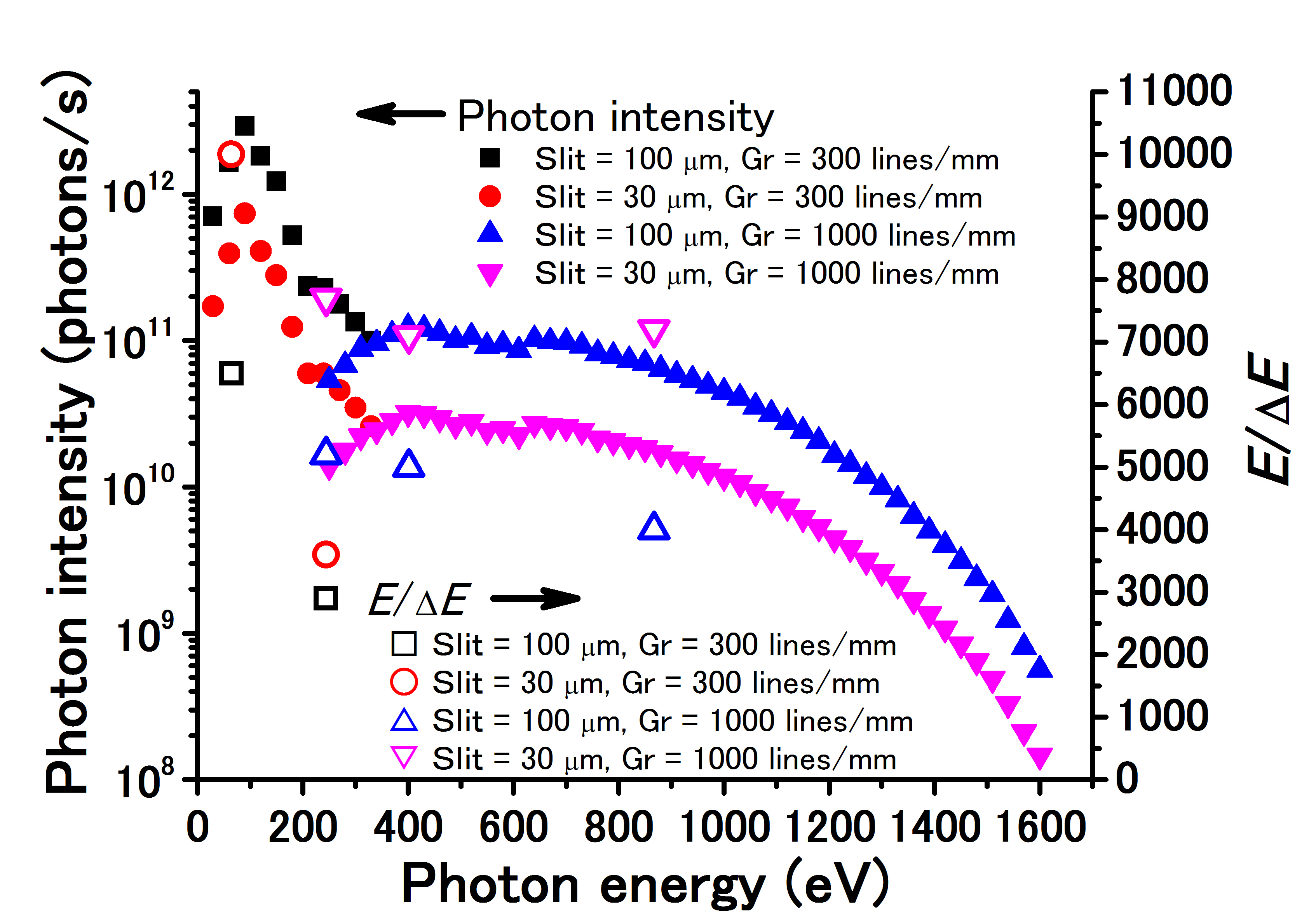
Fig. 3. Typical photon intensity and photon energy resolution(E/ΔE)in the photon energy region of 30 - 1600 eV [3]。
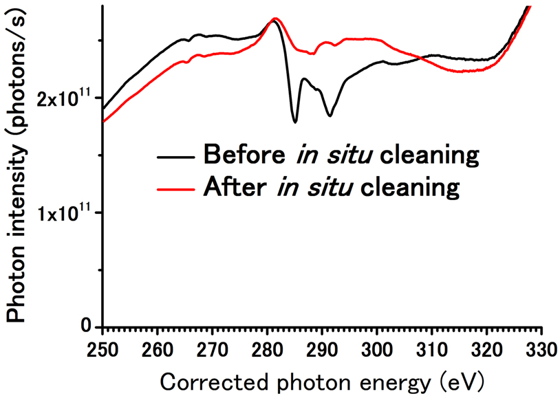
Fig. 4. Typical photon intensity in the carbon K-edge region [6]。
3. Apparatus for monitoring of the photon beam
A UHV chamber (the Monitor chamber, Fig. 5) is placed downstream of the M3 chamber to monitor the photon flux and to attenuate higher-order diffraction. The top conflat flange is installed together with three linear feedthroughs. The first one is equipped with Si and Mg filters to attenuate higher harmonics with photon energies of >98 eV and >49 eV, respectively. These filters are used for photoelectron spectroscopy in the VUV region to suppress signals derived from higher-order diffraction. On the second feedthrough, a gold mesh with a transmittance of 77% and a sapphire plate are attached to monitor the relative photon flux and the photon-beam position, respectively. The same chamber is also furnished with a gold evaporator. On the third feedthrough, a silicon photodiode is mounted to measure the absolute photon flux.
For the estimation of the photon-energy resolution and the calibration of photon energy, another UHV chamber (Fig. 6) is connected to the Monitor chamber. For accurate calibration, gas inlet for CO2, N2, O2 and noble gases, and an ion detector are also provided. Fig. 7 shows typical NEXAFS spectra of HOPG in the carbon K-edge region measured at BL-13A.
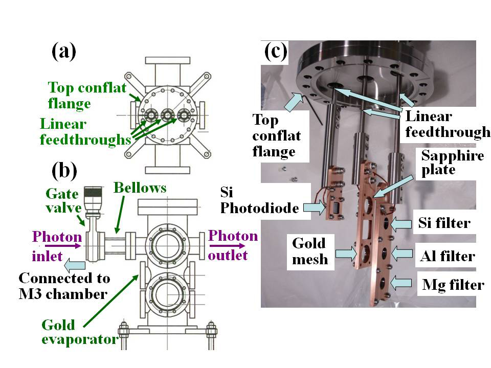
Fig. 5 (a) Top and (b) side views of the photon monitor chamber. (c) Top conflat flange is attached with three linear feedthroughs.
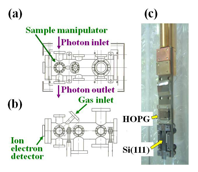
Fig. 6 (a) Top and (b) side views of the Calibration chamber. (c) The end of the sample rod is placed on the top of the sample manipulator on the chamber. HOPG stands for highly oriented pyrolytic graphite.
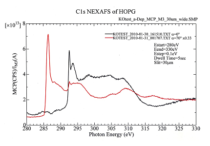
Fig. 7. Typical NEXAFS spectra of HOPG in the carbon K-edge region measured at BL-13A by Prof. K. K. Okudaira (Chiba Univ.)
4. Apparatus for the study of surface chemistry using ARPES, XPS, and XAS
Figure 8 shows the apparatus used for the study of surface chemistry using ARPES, XPS, and XAS. The apparatus consists of the main UHV chamber equipped with an electron-energy analyzer (Gamma Data/Scienta, SES200), a sample-preparation UHV chamber, and a UHV chamber for the evaporation of organic materials. The sample can be transferred among UHV chambers with a transfer rod. The sample-holder acceptors in the main and sample-preparation chambers are both equipped with a sample heating and cooling system, as shown in Fig. 9. The estimated overall electron-energy resolution is shown in Fig. 10. Some typical experimental data are shown in Figs. 11 and 12.
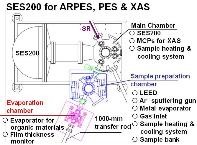
Fig. 8. Apparatus for the study of surface chemistry using ARPES, XPS, and XAS.
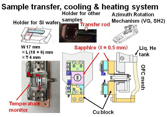
Fig. 9. Sample holders and sample-holder acceptor.
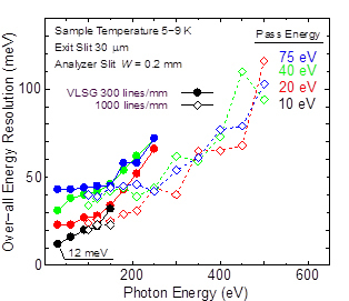
Fig. 10. Overall electron-energy resolution as estimated with an electron-energy analyzer and an evaporated gold film at 5–9 K.
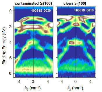
Fig. 11.Typical ARPES spectra of contaminated and clean Si(100) measured with SES-200 at BL-13A by K. Ozawa (Tokyo Inst. of Technol.).
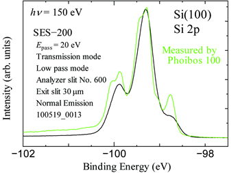
Fig. 12.Typical Si-2p photoelectron spectra of Si(100) measured with SES-200 at BL-13A by . K. Ozawa (Tokyo Inst. of Technol.).
5. BL-13B
A branch beamline, BL-13B, has been constructed for photoelectron spectroscopy (Fig. 13) in March, 2013. It involves a plane mirror to suppress higher harmonics (Fig. 14), an exit slit, post-focusing mirrors, and a photon monitor system. BL-13B is now under commissioning and will be opened for users in October, 2013.
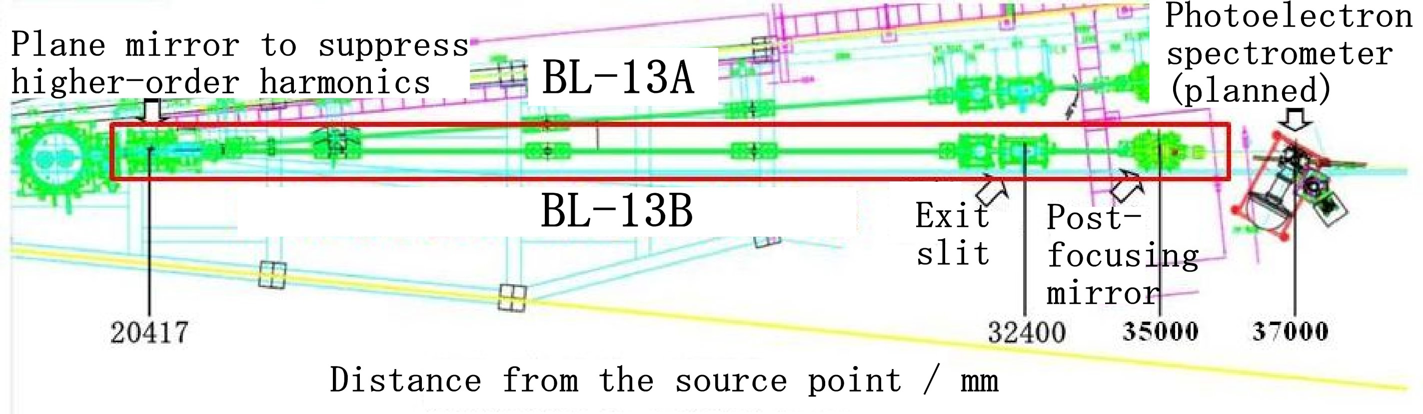
Fig. 13. A branch beamline, BL-13B, for photoelectron spectroscopy.
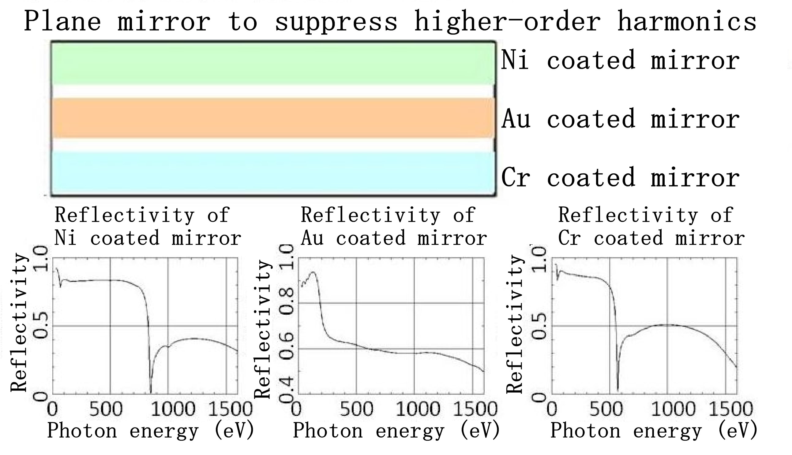
Fig. 14. Plane mirror to suppress higher harmonics.
6. References
[1] K. Mase, A. Toyoshima, T. Kikuchi, H. Tanaka, K. Amemiya, and K. Ito, AIP conference proceedings 1234, 703 (2010).
[2] A. Toyoshima, H. Tanaka, T. Kikuchi, K. Amemiya and K. Mase, J. Vac. Soc. Jpn. 54, 580 (2011).
[3] A. Toyoshima, T. Kikuchi, H. Tanaka, K. Mase, K. Amemiya, and K. Ozawa, J. Phys.: Conf. Ser. 425, 152019 (2013).
[4] K. Amemiya and T. Ohta, J. Synchrotron Rad. 11, 171 (2004).
[5] S. Sasaki, S. Yamamoto, T. Shioya, and H. Kitamura, Rev. Sci. Instrum. 60, 1859 (1989).
[6] A. Toyoshima, T. Kikuchi, H. Tanaka, J. Adachi, K. Mase, and K. Amemiya, J. Synchrotron Rad. 19, 722 (2012).
Last updated: 2013-04-19